
Why a concrete building can suffer from “hidden rust”
Reinforced concrete appears solid and permanent, yet one of its most important components is hidden from view: the steel reinforcement. In good-quality concrete, the steel is normally protected by the concrete's highly alkaline environment. This alkalinity creates a very thin, stable film on the steel surface, often called the passive layer. As long as this protective condition remains, the reinforcement can remain serviceable for decades.
Problems begin when aggressive substances reach the steel. Carbon dioxide from the atmosphere can gradually reduce the alkalinity of the concrete through carbonation. Chlorides may enter from coastal air, saline groundwater, industrial exposure, contaminated materials or de-icing salts in relevant climates. Cracks, porous concrete, inadequate cover, repeated wetting, water leakage and poor drainage make this process faster.
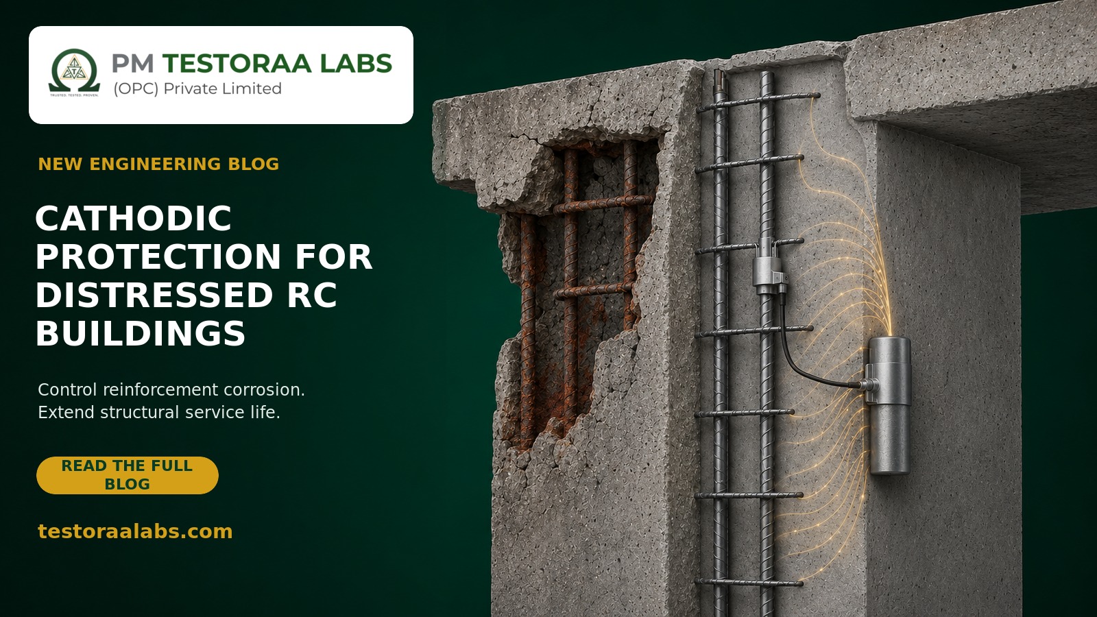
Once the passive layer is destroyed, portions of the reinforcement behave like tiny anodes and cathodes connected through moist concrete. At the anodic locations, iron is converted into corrosion products—rust. Rust occupies a larger volume than the original steel. This expansion generates pressure within the concrete, leading first to internal cracking, then longitudinal cracks along the bars, delamination and finally spalling.
Plain-language explanation: Reinforcement corrosion is similar to a battery operating inside the concrete. Moist concrete acts as the medium through which electrical charge moves. Cathodic protection changes this electrochemical arrangement so that the reinforcement is forced to behave as the protected cathode.
Cathodic protection, commonly abbreviated as CP, is one of the few repair technologies capable of directly controlling this electrochemical corrosion process. The U.S. Federal Highway Administration has described cathodic protection as a proven rehabilitation technique for arresting corrosion in salt-contaminated reinforced-concrete bridge decks, irrespective of the chloride content remaining in the concrete. However, successful application requires far more than placing a few pieces of zinc near rusty bars. It is an engineered system that must be assessed, designed, commissioned and monitored.
What cathodic protection actually does
Corrosion involves the flow of electrons through steel and ionic current through concrete. Cathodic protection supplies protective direct current to the reinforcement. This shifts the electrochemical condition of the steel in a direction that reduces the rate at which iron dissolves.
Simplified protective-current path
Anode
Sacrificial zinc or an engineered ICCP anode supplies protective current.
Sacrificial zinc or an engineered ICCP anode supplies protective current.
Reinforcement becomes the cathode
Corrosion activity is reduced when adequate current reaches the steel.
Corrosion activity is reduced when adequate current reaches the steel.
Concrete is the electrolyte between the anode and reinforcement. Connections and current distribution must be verified in the field.
CP controls future electrochemical deterioration. It does not reverse damage that has already occurred. A bar that has lost 25% of its cross-sectional area will not regain that steel after CP is switched on. Concrete that has separated from the member will not rebond by itself. A weakened beam will not become stronger merely because corrosion has slowed.
Essential distinction: Cathodic protection is a corrosion-control measure, not a substitute for structural repair. Unsafe members may require temporary shoring, replacement or supplementation of reinforcement, section enlargement, steel plate bonding, FRP strengthening, jacketing or another engineered intervention before CP is commissioned.
When should cathodic protection be considered?
CP is most valuable when reinforcement corrosion is active or highly probable over a broad area, while a significant proportion of the existing concrete remains structurally usable. It can be especially attractive where removing every part of chloride-contaminated or carbonated concrete would be excessively disruptive, expensive or damaging to the building.
Situations that may favour CP
- Widespread chloride contamination
- Recurring corrosion after conventional patch repairs
- Balconies, façades, parking structures and wet zones
- Coastal or industrial exposure
- Large areas where sound contaminated concrete is to remain
- A need for measurable long-term corrosion control
Situations requiring caution
- Severely reduced or buckled reinforcement
- Loss of bond or anchorage
- Unstable members or falling-concrete hazards
- Unknown reinforcement continuity
- Prestressed or post-tensioned steel
- Conductive fibres or complex embedded metals
Not every rusty building requires full CP. If carbonation is shallow, contamination is limited and moisture ingress can be reliably stopped, correctly executed conventional repairs may be adequate. Conversely, repeatedly patching isolated spalls in a chloride-contaminated façade can transfer corrosion activity to the steel just outside the new patch. This is called the incipient-anode or ring-anode effect. Local galvanic anodes are often used around patch boundaries to reduce that risk.
Engineering assessment before selecting a system
The visible crack is only a symptom. A scientific repair plan must establish the cause, distribution and structural consequence of deterioration. ACI 364.1R describes assessment as a process that includes document review, preliminary and detailed investigation, field observation, sampling, testing, evaluation and reporting. For Indian projects, the assessment and structural checks should also be coordinated with applicable provisions of IS 456, IS 15988 and other relevant Indian Standards, project specifications and statutory requirements.
| Investigation | What it tells the engineer | Important limitation |
|---|---|---|
| Visual survey and distress mapping | Locations of cracking, leakage, rust staining, spalling, deformation and earlier repairs | Does not reveal all hidden corrosion or delamination |
| Hammer sounding or delamination survey | Potentially debonded or hollow-sounding concrete | Result depends on access, geometry and operator judgement |
| Rebar scanning and cover measurement | Approximate bar position, spacing and concrete cover for testing and anode detailing | Congested reinforcement and embedded services can complicate interpretation |
| Half-cell potential mapping | Spatial pattern of corrosion probability or electrochemical activity | Potential alone is not a direct corrosion-rate or section-loss measurement |
| Concrete surface resistivity | How readily protective or corrosion current may travel through the concrete | Strongly influenced by moisture, temperature and test arrangement |
| Corrosion-rate measurement | Estimate of current corrosion activity at the time of testing | Requires suitable equipment and careful interpretation |
| Carbonation-depth testing | Whether reduced alkalinity has reached the reinforcement depth | Local samples may not represent the entire member |
| Chloride-content profile | Amount and depth distribution of chloride contamination | Requires representative sampling and laboratory analysis |
| Selective breakout and bar measurement | Actual corrosion condition, pitting, bond and remaining bar diameter | Intrusive; locations must be selected and reinstated properly |
| Structural analysis | Whether the remaining member has adequate capacity and serviceability | Depends on reliable geometry, loading, material and deterioration data |
Electrical continuity is a design issue
The reinforcement intended to receive protection must normally form a continuous electrical network. Separate pours, precast components, couplers, coated bars and previous repairs may leave isolated areas. The engineer therefore performs continuity testing and provides designed continuity bonds where necessary. At the same time, unintended contact between the anode and reinforcement must be prevented because it can short-circuit the system.
Moisture and concrete resistivity matter
Concrete is not a metal conductor; current travels through its pore solution. Very dry or highly resistive concrete can limit current distribution, particularly for galvanic systems. Saturated zones behave differently from dry façades. This is why an anode layout cannot be copied blindly from another building or selected only by floor area.
The three principal protection approaches
1. Discrete galvanic anodes in concrete repairs
Discrete galvanic anodes usually contain an activated zinc core. During a patch repair, each anode is secured electrically to cleaned reinforcement and encapsulated in a compatible repair material. Zinc is more electrochemically active than reinforcing steel, so it preferentially corrodes and supplies protective current to nearby steel.
They are commonly installed around the perimeter of a repair or at selected locations in sound but contaminated concrete. ACI RAP-8 explains that embedded galvanic anodes can reduce corrosion activity near the installed anode and can be used to protect steel surrounding a patch where corrosion is likely to initiate or recur.
The word nearby is important. A few patch anodes do not automatically protect an entire column, slab or building. Their effective range and service life depend on anode capacity, spacing, reinforcement density, concrete resistivity, moisture and environmental exposure. The engineer should distinguish local galvanic corrosion control from a monitored whole-zone cathodic-protection system.
2. Distributed galvanic cathodic protection
Where larger areas require passive protection, a distributed galvanic system may use embedded zinc anodes, zinc mesh, sheet systems, sprayed zinc or purpose-designed galvanic jackets. No external rectifier is required; the electrochemical difference between the sacrificial anode and the reinforcement drives the current.
Galvanic systems are comparatively simple and generally have a lower risk of excessive current, but they offer less control over output. The anode is gradually consumed and must have adequate capacity for the intended design life. Long-term performance also depends on the anode remaining active and all electrical connections remaining intact.
3. Impressed-current cathodic protection (ICCP)
ICCP uses a low-voltage DC power supply, commonly a transformer-rectifier or controlled power unit. The positive terminal connects to a durable anode system; the negative terminal connects to the reinforcement. Possible anodes include mixed-metal-oxide-coated titanium mesh, ribbon or discrete anodes, conductive coatings and sprayed-metal systems. The exact choice depends on the exposure, geometry, finish, required life and maintainability.
Because the output can be adjusted, ICCP is well suited to large or variable corrosion zones. The building is divided into manageable electrical zones, each with appropriate steel connections, anode feeds, reference electrodes and monitoring points. This control is a major advantage—but it also means the system needs expert commissioning, a permanent power supply and planned inspection.
| Feature | Galvanic system | Impressed-current system |
|---|---|---|
| Source of current | Natural potential difference; sacrificial anode is consumed | External controlled DC power source |
| Control of current | Limited; responds to electrochemical conditions | Adjustable by zone |
| Typical use | Patch repairs, local zones and suitably designed distributed systems | Widespread or demanding corrosion conditions |
| Maintenance | Lower electrical maintenance, but anode consumption must be considered | Power, cabling, electronics, electrodes and output require monitoring |
| Risk if poorly designed | Insufficient current or short service life | Under-protection, over-protection, shorts or uneven current distribution |
How a cathodic-protection project is executed
- Make the building safe. Restrict access, remove immediate falling hazards and shore distressed structural members wherever the engineering assessment requires it.
- Define repair and protection zones. Combine visual mapping, delamination survey, electrochemical testing, contamination profiles and structural evaluation. Visible spalls alone are not an adequate basis.
- Remove unsound concrete carefully. Avoid damaging sound reinforcement, embedded services and adjacent concrete. Saw-cutting and breakout depths must be controlled.
- Inspect and restore reinforcement. Clean exposed steel, measure actual section loss and check anchorage. Add or replace reinforcement where structural calculations require it.
- Establish steel continuity. Test each intended protection zone and install durable continuity connections. Provide dedicated negative connections to the reinforcement.
- Install the selected anode system. Place discrete anodes, mesh, ribbon, coating or another specified system at the designed spacing and orientation. Maintain separation from the reinforcement except at designed electrical connections.
- Install reference electrodes and monitoring points. Permanent sensing and test facilities allow the engineer to verify that all critical areas meet the intended protection criteria.
- Apply compatible repair materials. Repair mortar or concrete must meet structural, dimensional, durability and electrical-resistivity requirements. A very resistive material can obstruct protective current.
- Correct the exposure source. Repair leaks, joints, drains, waterproofing, slopes and façade details. CP is not a licence to allow continuous water ingress.
- Perform pre-energisation tests. Confirm polarity, cable insulation, anode and steel continuity, absence of short circuits, reference-electrode response and baseline steel potentials.
- Commission in controlled stages. For ICCP, begin at an engineered low output, interrupt the current for measurements, examine current distribution and progressively adjust each zone.
- Document and monitor. Record as-built layouts, connections, baseline readings, commissioning data and future monitoring intervals. Retain this information for the building's service life.
How engineers know whether the steel is protected
Simply observing a voltage at the control panel does not prove that every bar is protected. Current may concentrate near anodes, avoid dry areas or fail to reach electrically isolated reinforcement. Performance must be assessed using embedded reference electrodes and recognised criteria.
A commonly used verification concept is depolarisation: after the protective current is interrupted, the engineer observes how the steel potential changes over a defined period. A potential-decay criterion—often discussed as approximately 100 mV under appropriate test conditions—is widely used, but it must not be treated as a stand-alone number copied into every project. The applicable standard, exposure, measurement procedure, reference electrode stability, interference and safety of the steel system must all be considered.
ISO 12696:2022 specifies performance requirements for cathodic protection of steel in cement-based concrete in new and existing buildings and civil-engineering structures. It requires sufficient performance-monitoring provisions to demonstrate that the intended protection criteria are met throughout the protected parts of the structure.
A useful commissioning question is not “Is current flowing?” but “Has adequate, safe and reasonably uniform polarisation been demonstrated at representative and critical locations?”
Monitoring and maintenance throughout service life
Cathodic protection is a managed asset, not a one-time coating application. Inspection frequency should be established in the design and operation manual. More frequent review is appropriate during initial commissioning and after major repairs, power interruptions, flooding, façade work or unexplained changes in readings.
Depending on the system, monitoring may include:
- Zone voltage and current output
- Current density and distribution
- Instant-off potential and depolarisation response
- Reference-electrode stability
- Anode-circuit and reinforcement continuity
- Insulation resistance and short-circuit checks
- Condition of junction boxes, cables and control equipment
- New cracking, leakage, delamination or spalling
- Performance of waterproofing, joints and drainage
- Trend comparison with baseline and previous readings
A single abnormal reading should be investigated, not automatically “corrected” by increasing the voltage. The cause may be a dry concrete zone, a failed reference electrode, a damaged cable, a short circuit, loss of continuity or an actual change in steel demand.
Common mistakes that shorten repair life
1
Treating CP as strengthening
Corrosion control cannot compensate for inadequate remaining bar area, lost anchorage, poor concrete capacity or an unsafe load path.
2
Using one test in isolation
Half-cell potential, rebound hammer or UPV alone cannot establish corrosion severity, steel loss and structural adequacy.
3
Ignoring electrical continuity
Isolated bars may receive little or no protection even when the control unit appears to operate normally.
4
Wrong repair-mortar resistivity
An electrically incompatible patch can create uneven current distribution and reduce system performance.
5
No permanent monitoring
Without reference electrodes and accessible test points, protection cannot be reliably demonstrated over time.
6
Leaving the water source active
Leakage and poor drainage continue to damage finishes, concrete and unprotected embedded components even if steel corrosion is controlled.
Special caution for prestressed and post-tensioned structures
Prestressing steel is highly stressed and may be more sensitive to hydrogen-related damage if electrochemical systems are incorrectly designed or operated. Ducts, anchorages, strands and electrically isolated components also make investigation more complex. Excessive polarisation must be avoided. Such structures require a specialist with demonstrated experience in cathodic protection and prestressed-concrete durability.
Similar specialist review is needed when a member contains conductive carbon or steel fibres, epoxy-coated bars, stainless steel, dissimilar embedded metals, aluminium components or sensitive electrical systems. ISO 12696 identifies specific scope conditions and exclusions; the project engineer must verify applicability rather than assume that a conventional reinforced-concrete detail is suitable.
A practical decision framework for building owners
| Observed condition | Likely engineering response |
|---|---|
| Small isolated spall, low surrounding contamination | Investigate the cause; conventional repair and moisture-control measures may be sufficient. |
| Patch repair surrounded by chloride-contaminated or carbonated concrete | Consider perimeter galvanic anodes to reduce incipient-anode corrosion, subject to design. |
| Several active corrosion zones over a moderate area | Evaluate a designed distributed galvanic system or zoned ICCP after structural repairs. |
| Widespread active corrosion with extensive sound contaminated concrete | ICCP may offer controlled, measurable whole-zone protection and reduce the extent of concrete removal. |
| Major section loss, bond failure, deformation or unstable concrete | Immediate safety action and structural rehabilitation are the priority; CP may be added only as part of the durability strategy. |
Life-cycle cost should be compared, not just initial price. A low-cost patch that fails repeatedly can be more expensive and disruptive than a properly investigated durability system. The comparison should include structural repair, access and scaffolding, anode system, finishes, power, monitoring, maintenance, waterproofing and expected service life.
Frequently asked questions
Can cathodic protection repair an already corroded bar?
No. It can slow or arrest continuing corrosion when properly designed, but it cannot recreate lost steel. The remaining bar area must be measured or reliably assessed, and deficient reinforcement must be replaced or supplemented.
Are zinc anodes placed in every concrete patch?
Not automatically. Their need, type, capacity and spacing depend on the cause and extent of corrosion, surrounding contamination, moisture, steel density and intended service life. They are most useful where corrosion could recur around a repair boundary.
Does ICCP use dangerous electricity?
ICCP normally operates at low DC voltage, but it remains an engineered electrical system. Correct polarity, insulation, zoning, enclosures, cabling, commissioning and maintenance are essential.
Can half-cell potential testing alone confirm that CP is required?
No. Half-cell mapping is valuable for identifying electrochemical patterns, but it does not directly measure bar section loss or structural capacity. It should be interpreted with resistivity, corrosion rate, carbonation, chloride, breakout and structural data.
Will waterproofing alone stop reinforcement corrosion?
Stopping water ingress is crucial, but corrosion may continue where sufficient moisture and contamination already exist. Waterproofing, repair and electrochemical control each address different parts of the problem.
How long does a cathodic-protection system last?
There is no universal life. Galvanic life depends on anode capacity and current demand. ICCP anodes can provide long service when operated within their rated capacity, but power, wiring, reference electrodes and control equipment require maintenance. The design should state the intended life and renewal strategy.
Can cathodic protection be installed in an occupied building?
Often yes, with phased access, dust and noise controls, safety barriers and careful coordination. However, unstable concrete, temporary shoring, façade access and electrical installation may require restricted zones or temporary relocation.
Technical references and guidance
- ISO 12696:2022, Cathodic protection of steel in concrete.
- ACI 222R-19, Guide to Protection of Reinforcing Steel in Concrete against Corrosion.
- ACI RAP-8, Installation of Embedded Galvanic Anodes.
- ACI 364.1R-19, Guide for Assessment of Concrete Structures before Rehabilitation.
- ACI CODE-562-21, Assessment, Repair, and Rehabilitation of Existing Concrete Structures.
- Federal Highway Administration, Utilization of Cathodic Protection to Extend the Service Life of Existing Reinforced Concrete Structures.
- Federal Highway Administration, Long-Term Effectiveness of Cathodic Protection Systems on Highway Structures.
- IS 456:2000, Plain and Reinforced Concrete—Code of Practice, including applicable amendments.
- IS 15988:2013, Seismic Evaluation and Strengthening of Existing Reinforced Concrete Buildings—Guidelines, where applicable to the assessment and strengthening scope.
- IS 13311 (Parts 1 and 2), Non-destructive Testing of Concrete—Methods of Test, for relevant UPV and rebound-hammer investigations.
Concerned about corrosion, cracking or concrete spalling?
Testoraa Labs provides structured condition assessment, non-destructive testing, reinforcement mapping and engineering inputs for repair planning. The correct first step is diagnosis—not an off-the-shelf repair product.
Call +91 97870 59595Request an Inspection on WhatsAppProfessional note: This article is for general technical awareness. It is not a project-specific design, safety certificate, method statement or substitute for inspection by a qualified structural and cathodic-protection professional. Distressed buildings may present falling-object and structural-collapse hazards; restrict access and seek an engineering assessment where significant cracking, deflection, exposed reinforcement or spalling is observed.