
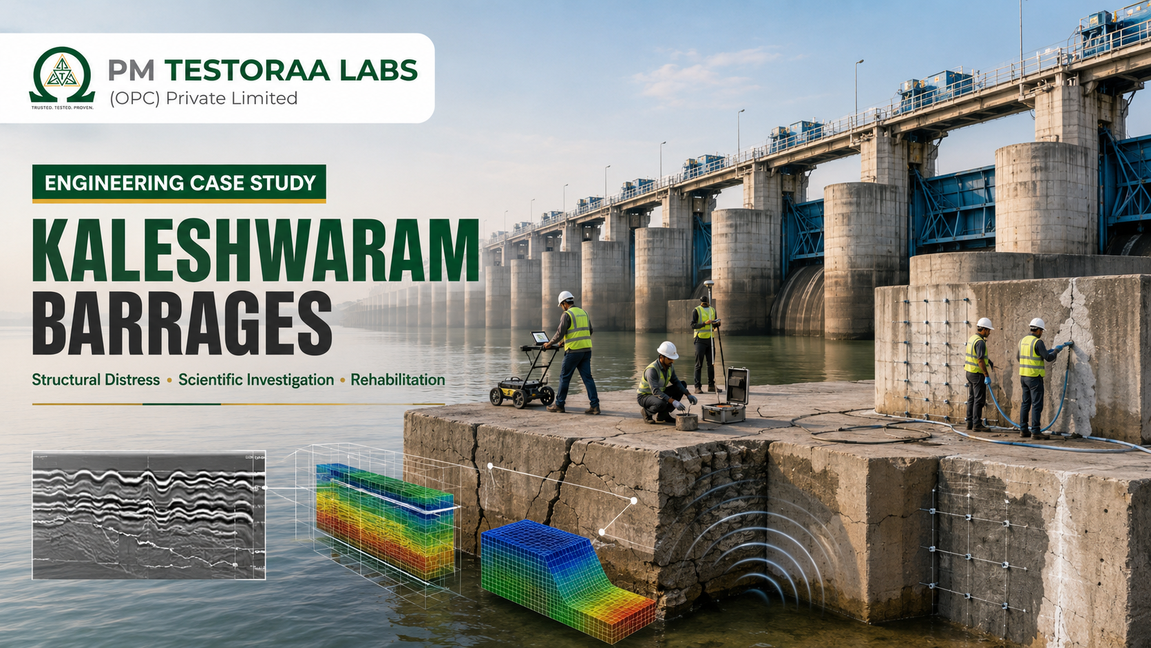
Engineering Case Study · Hydraulic Infrastructure
Kaleshwaram Barrages: Structural Distress, Scientific Investigation & Rehabilitation
A clear, evidence-led review of the Medigadda, Annaram and Sundilla barrages—how distress can develop, how engineers investigate it, and what must be proved before rehabilitation and safe recommissioning.
Why the Kaleshwaram barrages matter
The Kaleshwaram Lift Irrigation Project is not one isolated structure. It is a large water-transfer system in which barrages, pump houses, reservoirs, tunnels, pipelines and canals must work in sequence. At the river end of that chain, the Medigadda, Annaram and Sundilla barrages create the water levels needed for staged lifting from the Godavari.
The Comptroller and Auditor General of India describes the wider scheme as comprising seven links and 56 packages, including three barrages, 14 reservoirs and 31 lifts. Water is first intercepted at Medigadda and then moved progressively through the system. This interconnected arrangement means the serviceability of each barrage affects more than its own gates and concrete: it influences pumping availability, upstream and downstream water levels, operating rules and the reliability of the complete lift-irrigation chain.
Public concern increased after visible distress occurred at Medigadda in October 2023. The National Dam Safety Authority subsequently examined the three barrages and, in its final report listed on the NDSA website, recommended rehabilitation of Medigadda, Annaram and Sundilla. Public reporting of that report states that Block 7 at Medigadda had suffered irreversible damage, while all three sites required a scientific, multidisciplinary response.
Scope and neutrality: This article is an independent educational engineering review based on official documents and publicly reported findings. It does not assign responsibility, determine legal liability or replace the conclusions of NDSA, CWC, the project owner or appointed expert agencies. Where a mechanism is discussed, it is presented as an engineering possibility to be tested against evidence—not as a final cause.
As of the official Telangana update dated 20 April 2026, detailed geotechnical and geophysical investigations were continuing at Medigadda. The update referred to tests around piers 20, 21 and 22, ground-penetrating radar, sample collection from 520 bore points for analysis at the Central Water and Power Research Station, and cross-hole seismic testing of sealant piles. The same update stated that restoration would begin only after the technical condition was fully understood and the samples analysed, with NDSA guidance and approvals at each stage.
The central lesson in plain language: cracked concrete is sometimes only the visible symptom. The real problem may lie in moving soil, lost foundation support, seepage, uplift pressure, scour, construction details, gate operation—or several of these acting together. Good engineering repairs the cause and then verifies the structure, instead of simply covering the symptom.
Understanding the three-barrage system
A barrage looks similar to a low dam, but its principal purpose is usually to regulate river level and divert water through a series of controllable gates. A conventional storage dam resists a large, more permanent difference in water level. A barrage generally has many gate bays, a broad reinforced-concrete floor or raft, piers supporting the gates and bridges, upstream and downstream cut-offs, and protective works that manage the high-energy water leaving the gates.
The three Kaleshwaram barrages stand on river foundations that include permeable alluvial material. Water therefore does not act only on the exposed concrete. It also tries to travel beneath and around the floor. Engineers must control this hidden seepage path so that pressure under the raft remains within design limits and soil particles are not carried away.
Raft or floorThe heavy reinforced-concrete base spreads loads and provides an impervious water path. Its contact with the foundation is essential; an unseen cavity can change the way it bends and transfers forces.
Piers and gatesPiers support gate guides, operating equipment and bridge loads. Their alignment matters because even moderate settlement or rotation can disturb gate clearances and concentrate stress.
Cut-offs and seal pilesVertical barriers lengthen the seepage path and reduce the exit gradient. Their continuity, embedment and connection to the raft influence seepage safety.
Stilling basin and apronThese downstream elements dissipate the energy of released water and protect the riverbed. If protection is lost, scour can migrate toward the main structure.
Drainage and filtersProper drainage relieves pressure, while graded filters allow water to escape without carrying soil. Blocked drains or defective filter transitions can alter performance.
Joints and blocksA long barrage is divided into structural blocks so that movement can be controlled. Joint movement, water stops and cross cut-offs require careful inspection.
These components behave as one soil–water–structure system. A pier cannot be assessed only as a concrete column, and the raft cannot be assessed only as a slab. The engineer must model hydraulic pressure, soil stiffness, foundation contact, structural stiffness, gate loads and construction joints together.
What has been documented
A responsible case study separates observations from interpretations. An observation is something measured or recorded: a displaced pier, a cracked raft, a cavity, a damaged apron or an abnormal instrument reading. An interpretation explains how it may have happened. Final interpretation requires multiple, independent lines of evidence.
Before the October 2023 event
The CAG performance audit, published in 2024, recorded damage to downstream cement-concrete blocks and aprons observed during audit inspections at the three barrages. Those observations are relevant to hydraulic and maintenance history, but they do not by themselves establish the later root cause.
The CAG performance audit, published in 2024, recorded damage to downstream cement-concrete blocks and aprons observed during audit inspections at the three barrages. Those observations are relevant to hydraulic and maintenance history, but they do not by themselves establish the later root cause.
October 2023
Visible subsidence and distress were reported in Block 7 of the Medigadda barrage. The event brought pier movement, raft behaviour, foundation support and operational safety under intense technical scrutiny.
Visible subsidence and distress were reported in Block 7 of the Medigadda barrage. The event brought pier movement, raft behaviour, foundation support and operational safety under intense technical scrutiny.
NDSA investigation and final report
NDSA constituted a committee to inspect and study the designs and construction of Medigadda, Annaram and Sundilla. Its final report, submitted in April 2025 and listed on the NDSA reports page, called for rehabilitation of all three barrages.
NDSA constituted a committee to inspect and study the designs and construction of Medigadda, Annaram and Sundilla. Its final report, submitted in April 2025 and listed on the NDSA reports page, called for rehabilitation of all three barrages.
2025 recommendations reported publicly
Public summaries of the NDSA report described irreversible damage to Medigadda Block 7, cracked or displaced piers and raft, cavities under the raft and the need for fresh finite-element analysis incorporating soil–structure interaction. They also reported that Block 7 should not be used for gate operation and would require safe decommissioning/removal or engineered stabilisation without harming adjoining blocks.
Public summaries of the NDSA report described irreversible damage to Medigadda Block 7, cracked or displaced piers and raft, cavities under the raft and the need for fresh finite-element analysis incorporating soil–structure interaction. They also reported that Block 7 should not be used for gate operation and would require safe decommissioning/removal or engineered stabilisation without harming adjoining blocks.
April 2026 scientific investigation
The Telangana Government reported an expanded programme involving bore points, GPR, geotechnical and geophysical tests, sampling for CWPRS analysis and cross-hole seismic testing. It stated that restoration decisions would follow complete technical understanding and approvals.
The Telangana Government reported an expanded programme involving bore points, GPR, geotechnical and geophysical tests, sampling for CWPRS analysis and cross-hole seismic testing. It stated that restoration decisions would follow complete technical understanding and approvals.
The words distressed, damaged and unserviceable are not interchangeable. A distressed component is showing abnormal behaviour that requires evaluation. A damaged component has a physical defect. An unserviceable component cannot safely perform its intended function under the specified conditions. The engineering team must define the applicable condition for every block, gate and foundation zone, rather than giving one label to an entire complex.
Why all three barrages are investigated: Similar design concepts, construction methods, foundation environments or operating demands can create common vulnerabilities even when visible damage differs. A system-wide investigation is therefore a precautionary engineering response; it is not proof that every barrage or block has suffered identical damage.
How structural distress can develop
The following mechanisms are important in barrage forensics. They may act alone, but serious incidents often result from interaction. The purpose of investigation is to determine which mechanisms are present, their sequence, and whether they are active or stable.
1. Loss of foundation support and differential settlement
A barrage raft is designed on assumed foundation stiffness and contact. If soil beneath one zone compresses, erodes or becomes voided, the raft may bridge over the weak area. Bending moments and shear forces then become very different from the original design assumptions. Piers may tilt, adjacent blocks may move by different amounts, joints may open and gate slots may lose alignment.
Differential settlement is more damaging than uniform settlement because connected components cannot move together. Even a movement that appears modest compared with the overall size of a barrage can be critical to a gate that needs controlled clearances.
2. Sand piping and internal erosion
“Piping” does not mean a water pipe. It describes the progressive removal of soil particles by seepage. Water moving through permeable foundation material applies force to the grains. If the hydraulic gradient becomes too high, fine particles can migrate. Small flow channels may enlarge, support can be lost, and a cavity can form beneath the raft or near a cut-off.
Hydraulic gradient, i = difference in water head ÷ seepage length
This simple relationship explains why cut-offs and a sufficiently long floor are important: they lengthen the seepage path. Real foundations are three-dimensional and layered, however, so engineers use seepage analysis, piezometer data, permeability tests and soil gradation to estimate the risk. Filling a cavity without controlling the pathway that created it can provide only temporary relief.
3. Uplift pressure beneath the floor
Seepage water exerts upward pressure on the raft. The structure’s self-weight and structural capacity must resist this uplift with the specified safety margin. If actual pressure is higher than assumed, drains are ineffective, a cut-off is discontinuous or the foundation contact is disturbed, the effective downward force can reduce. This may promote cracking, separation or instability.
Uplift is invisible from above. It is inferred from piezometers, drain flows, seepage models, relief-well behaviour and the condition of joints. Reliable rehabilitation therefore needs both pressure measurement and a calibrated seepage model.
4. Scour and downstream protection damage
Water released below a gate has high velocity and energy. The stilling basin is designed to form a hydraulic jump and dissipate energy before the flow reaches erodible river material. Concrete blocks, filters, aprons and launching protections extend this defence downstream. Floods, non-uniform gate opening, sediment concentration and local flow patterns can damage or displace protection.
Once a scour hole forms, it can deepen or migrate toward the barrage. Bathymetric survey, sonar profiling, underwater inspection and hydraulic modelling help distinguish a stable riverbed feature from an advancing threat to foundation support.
5. Structural detailing, materials and construction effects
Concrete strength is only one part of structural quality. Engineers also examine reinforcement position, anchorage, construction joints, water stops, lift joints, compaction, curing, temperature cracking, cover, embedded gate parts and the connection between raft and pier. As-built geometry and construction sequence can alter load paths.
Core tests, petrography and non-destructive testing may identify variability or deterioration, but no single rebound-hammer number can declare a barrage safe or unsafe. Large hydraulic structures require test zoning, correlation with cores, statistical interpretation and structural analysis.
6. Gate operation and hydraulic loading
Gate-opening patterns change flow concentration, upstream water level, differential head and downstream turbulence. Operating records must be compared with the approved reservoir operation schedule and the hydraulic model. This does not mean gate operation is automatically the cause of distress. It means operating loads are part of the complete evidence set.
7. Block interaction and progressive behaviour
Long barrages contain multiple blocks separated by joints. If one block moves, engineers must determine whether it can pull, push, leak toward or otherwise affect its neighbours. Survey monitoring across several blocks is essential. Safe removal or reconstruction of a severely damaged block is a temporary-works problem as well as a permanent-design problem; uncontrolled demolition could change water pressure, foundation confinement or load transfer.
Engineering rule: A credible root-cause statement must explain the location of damage, its geometry, the sequence of movement, the hydraulic conditions at the time, the subsurface evidence and the structural response. If it explains only the visible crack, it is incomplete.
The scientific investigation process
A major barrage cannot be diagnosed by one test or one consultant discipline. The investigation should progressively reduce uncertainty: first reconstruct what was designed and built, then map present condition, investigate hidden zones, test competing explanations and finally calculate how the damaged system behaves.
Secure the site and define operating restrictions. Establish exclusion zones, safe water levels, gate restrictions, emergency communication and monitoring frequency. Temporary safety decisions are based on consequence and uncertainty, not only on visible appearance.
Build a verified project record. Assemble design memoranda, geological logs, calculations, hydraulic model reports, drawings, revisions, method statements, concrete records, pile or cut-off records, photographs, instrumentation history, gate logs, flood hydrographs and maintenance reports. Compare issued-for-construction drawings with as-built survey data.
Create a common survey reference. Install stable external benchmarks and measure raft levels, pier coordinates, verticality, joint openings, gate geometry and bridge alignment. Repeat surveys using the same control network so that true movement is separated from measurement error.
Map visible and underwater condition. Record cracks by width, length, direction, depth and activity. Survey spalling, leakage, exposed reinforcement and joint condition. Use divers, remotely operated vehicles, sonar and bathymetry where water prevents direct inspection.
Investigate the foundation. Drill boreholes and collect disturbed and undisturbed samples where feasible. Conduct in-situ penetration, permeability, density and geophysical tests. Map soil layers, weak lenses, cavities, erosion pathways and the condition of cut-offs or seal piles.
Assess concrete and reinforcement. Use calibrated ultrasonic pulse velocity, rebound testing, impact-echo or tomography where suitable, rebar location, half-cell or resistivity testing where corrosion is relevant, and selected cores for strength and petrographic evaluation. Design the programme around engineering questions, not around a fixed list of instruments.
Reconstruct hydraulic and seepage behaviour. Review flood estimates, reservoir levels, gate sequences, sediment and river morphology. Model uplift, exit gradients, flow through defects, hydraulic-jump location and scour. Calibrate calculations against piezometers, drain flows and observed riverbed levels.
Analyse soil–structure interaction. Build a finite-element model that represents foundation layers, contact conditions, raft and piers, joints, gates and staged construction or damage. Test multiple credible parameter sets because soil stiffness and cavity extent are uncertain. A single colourful contour plot is not proof; sensitivity and validation matter.
Integrate evidence and rank hypotheses. Use an evidence matrix to show what supports or contradicts each possible mechanism. Identify remaining uncertainty and perform targeted supplementary tests before finalising rehabilitation.
What the principal tests can—and cannot—tell us
| Method | Engineering question | Important limitation |
|---|---|---|
| Ground-penetrating radar (GPR) | Are there reflections consistent with voids, interfaces or disturbed zones? | Depth and clarity depend on moisture, conductivity, reinforcement and soil type. An anomaly needs correlation with drilling or another method. |
| Boreholes and sampling | What materials and cavities exist at the drilled location? What are their properties? | A borehole samples a narrow column. Spacing and geological interpretation determine whether local findings represent a larger zone. |
| Cross-hole seismic testing | How do wave velocities vary between boreholes, and where may weak or discontinuous zones exist? | Results require good borehole geometry, coupling and specialist inversion; velocity is not a direct structural-capacity value. |
| Permeability and piezometers | How easily does water flow, and what pressure acts beneath the structure? | Readings vary with reservoir and river levels. Instruments need verified elevations, calibration and long-term trends. |
| Concrete cores | What are the in-place strength, density, composition and internal condition at sampled points? | Coring is local and intrusive. Results must account for orientation, diameter, moisture, reinforcement avoidance and representativeness. |
| UPV and other concrete NDT | Is concrete quality relatively uniform, and are there suspect zones requiring confirmation? | Velocity is affected by moisture, path length and reinforcement. It cannot independently provide a universal compressive-strength value. |
| Precise levelling and total-station survey | Are piers, raft levels or joints moving over time? | Benchmarks must be outside the moving zone, with consistent precision, temperature correction and repeatable observation procedures. |
| Bathymetry and sonar | Where are scour holes, displaced blocks and riverbed changes? | One survey is a snapshot. Repeat surveys after changing flows are necessary to establish progression. |
| Finite-element analysis | How might the soil, raft and piers respond under credible loading and damage scenarios? | Output is only as reliable as geometry, boundary conditions, material parameters and calibration. Uncertainty studies are essential. |
Why “520 bore points” is not the conclusion
The number of test locations indicates the scale of an investigation, but engineering quality depends on where those points are placed, how the samples are recovered, which laboratory tests are performed and how results are integrated spatially. The important deliverable is a defensible three-dimensional ground model showing stratigraphy, permeability, erosion or cavity zones, and the uncertainty between observations.
Similarly, drone-assisted or surface GPR can rapidly screen large areas, but it does not replace intrusive confirmation. A strong programme uses non-destructive methods for coverage and boreholes for ground truth. Where methods disagree, the team investigates the disagreement instead of averaging it away.
From investigation to rehabilitation
Rehabilitation is not a single repair specification. It is a controlled sequence that must restore foundation support, hydraulic safety, structural capacity, gate functionality and measurable reliability. The scope may differ between barrages and even between neighbouring blocks.
1. Temporary stabilisation and risk control
Before permanent work, the project may need temporary water-level restrictions, relief pumping, additional monitoring, local support, seepage control or protection against further scour. Every temporary measure requires its own design checks, inspection plan and trigger levels. Temporary works should not hide evidence needed for the forensic investigation.
2. Treatment of voids and weak foundation zones
Confirmed cavities may be filled using engineered grout, concrete or other suitable material, depending on access, water flow, void geometry and foundation compatibility. But injection pressure must be controlled; excessive pressure can lift a raft, open joints or force grout into unwanted pathways. Trial sections, volume–pressure records and verification holes are usually necessary.
If internal erosion caused a cavity, the seepage source and exit must be controlled through an integrated system that may include renewed cut-offs, filters, drainage, pressure relief, contact grouting or ground improvement. “Fill the hole” is not a complete design criterion.
3. Damaged-block strategy
For a severely damaged block, options may include stabilisation in place, partial dismantling and reconstruction, or complete controlled replacement. Selection depends on residual capacity, foundation condition, ability to isolate water, effect on adjacent blocks, constructability and long-term inspection. Public summaries of the NDSA report indicate that Medigadda Block 7 should not be used for gate operation and should be safely decommissioned/removed or stabilised without affecting adjoining blocks. The approved project-specific design must govern the chosen method.
Dismantling is not ordinary demolition. Engineers must model the stages because each cut changes mass, stiffness and load transfer. Instrumented hold points allow work to stop if adjacent piers move, seepage increases or foundation pressure changes unexpectedly.
4. Structural repair or reconstruction
Repair may involve crack injection, removal of unsound concrete, reinforcement replacement or supplementation, jacketing, post-installed anchors, joint renewal, raft reconstruction or pier replacement. The repair material should be compatible in stiffness, shrinkage, thermal behaviour and durability. A very strong patch can still perform poorly if it transfers stress abruptly into weaker original concrete.
Structural design must check dead load, hydrostatic pressure, uplift, silt pressure, gate and bridge loads, impact, seismic effects, temperature, construction stages, differential foundation movement and credible abnormal conditions. Soil–structure interaction should reflect the post-treatment foundation—not simply reuse original assumptions.
5. Hydraulic and downstream protection
Stilling basins, aprons, filters, toe protections and river-training works should be assessed against updated bathymetry, flood hydrology, sediment behaviour and gate-operation scenarios. Physical hydraulic models can be valuable where three-dimensional turbulence, non-uniform gate operation or mobile-bed effects are difficult to represent reliably by calculation alone. Numerical modelling and physical testing should support one another.
6. Gate and electro-mechanical restoration
Pier movement can alter guide alignment, seal compression, hoist geometry and bridge support. Gates should be inspected for distortion, corrosion, wheel or roller condition, embedded-part alignment, hoist loads, limit switches, backup power and emergency operation. Dry testing alone is not equal to operating under head; commissioning must be staged.
7. Independent review and regulatory approval
High-consequence rehabilitation benefits from an independent multidisciplinary panel covering structural, geotechnical, hydraulic, geological, construction and dam-safety expertise. The Dam Safety Act requires relevant BIS codes and guidelines to be used for design or safety evaluation and reasons to be furnished for departures. Public reporting of the NDSA recommendations also calls for CWC review of rehabilitation design because of its complexity.
No calendar date can certify safety. Public completion targets are planning information, not engineering acceptance criteria. Recommissioning should occur only after investigation, approved design, construction-quality verification, instrumentation baselines, staged testing and formal clearances are complete.
Recommended rehabilitation hold points
| Hold point | Evidence required before release |
|---|---|
| Investigation complete | Integrated ground model, concrete assessment, survey baseline, hydraulic review and closure of material data gaps. |
| Design approved | Checked calculations, staged-construction analysis, drawings, specifications, risk register, independent review and competent-authority approval. |
| Foundation treatment accepted | Grout records, verification holes/tests, permeability or contact checks, survey stability and as-treated model update. |
| Structural work accepted | Material certificates, concrete and weld tests, reinforcement and embedment records, dimensional survey, NDT and defect closure. |
| Dry commissioning | Gate alignment, hoist and power tests, controls, emergency operation, bridge and access inspection. |
| Controlled impounding | Approved filling schedule, trigger–action–response plan, staffed monitoring, emergency communication and low-head behaviour within limits. |
| Higher operating stage | Stable movement, uplift, seepage and gate performance under the previous stage, plus formal review before increasing head. |
| Post-monsoon acceptance | Inspection after representative flows, repeat bathymetry, instrument trend review and closure of emerging defects. |
Monitoring: proving behaviour over time
A repaired barrage is not validated by appearance alone. Instrumentation converts hidden behaviour into measurable trends. The system should answer four questions: Is the foundation moving? Is water pressure controlled? Is seepage carrying material? Are the raft, piers and gates remaining aligned?
MovementPrecise levelling points, total-station targets, GNSS where suitable, joint meters, crack gauges, tiltmeters and in-place inclinometers.
Water and seepageUplift-pressure cells or piezometers, observation wells, drain-flow measurement, turbidity or sediment observation and leakage mapping.
Structural responseSelected strain gauges, temperature sensors, vibration or gate-load monitoring, and repeat NDT at defined reference zones.
Riverbed and protectionRepeat bathymetry, sonar, marker blocks, underwater imagery and inspections following floods or unusual gate operations.
Readings need context. A piezometer value is meaningful only when linked to upstream level, downstream level, gate opening, rainfall, drain status and time. Dashboards should show trends and rates of change, not only green or red status. A sudden change may be more important than the absolute reading.
A trigger–action–response plan assigns warning and emergency levels to each key parameter. It states who receives the alarm, which readings must be verified, what operating restriction follows and when evacuation or emergency procedures apply. Thresholds should come from design analysis and baseline behaviour, then be refined with reviewed performance data.
Common-man example: A medical thermometer is useful because we know what temperature is normal for a person and what action follows a fever. Structural instruments work the same way: measurement, baseline, trigger and response must be defined together.
Engineering lessons beyond Kaleshwaram
The case is relevant to dams and barrages, but its principles also apply to bridges, industrial floors, retaining walls and distressed buildings.
Investigate before repairingA crack can result from shrinkage, corrosion, overload, settlement or thermal movement. Repairing before identifying the mechanism can waste money or conceal risk.
Look below groundFoundations and water often control what happens above. Settlement survey, soil investigation, drain inspection and groundwater data can be more informative than surface patching.
Combine testsVisual inspection, NDT, cores, rebar scanning, geotechnical data and analysis answer different questions. Confidence comes from agreement between methods.
Preserve recordsDesign calculations, revisions, test reports, photographs, as-built drawings and maintenance logs greatly improve forensic accuracy years later.
Design the repair sequenceRemoving a column jacket, opening a floor or unloading one structural zone can redistribute forces. Temporary stages require calculation and monitoring.
Verify after interventionStrengthening is complete only when workmanship is tested and the original abnormal behaviour has stabilised under service conditions.
Frequent mistakes in forensic rehabilitation
- Choosing grouting, jacketing or crack injection before completing the diagnosis.
- Treating one NDT result as a direct verdict on structural safety.
- Ignoring water pathways, drainage and seasonal groundwater variation.
- Using assumed as-built details without rebar scanning, openings or record verification.
- Analysing the repaired final state but not the temporary construction stages.
- Collecting instrument data without stable benchmarks, trigger values or assigned response actions.
- Setting an opening date first and forcing the technical programme to fit it.
“The repair method is the final answer to a chain of evidence—not the first item on the investigation checklist.”PM Testoraa Labs engineering principle
Standards, governance and technical references
Project-specific requirements, NDSA/CWC directions and approvals govern the actual rehabilitation. The following Indian framework is particularly relevant to investigation, design, inspection and operation. Editions, amendments and statutory applicability must be confirmed by the appointed designer at the time of use.
| Reference | Relevance |
|---|---|
| Dam Safety Act, 2021 | Establishes institutional responsibilities for surveillance, inspection, investigation, operation, maintenance, instrumentation, emergency planning and comprehensive safety evaluation of specified dams. |
| CWC, Guidelines for Safety Inspection of Dams | Provides a systematic framework for inspection of dams and allied structures, documentation of defects and safety evaluation. |
| IS 7720:1991 | Criteria for investigation, planning and layout for barrages and weirs. |
| IS 6966 (Part 1):1989 | Hydraulic design of barrages and weirs—guidelines for alluvial reaches, including seepage, scour and energy-dissipation considerations. |
| IS 11130:1984 | Criteria for structural design of barrages and weirs. |
| IS 11150:1993 | Construction of concrete barrages—code of practice. |
| IS 12892:1989 | Safety aspects of barrage and weir structures—guidelines. |
| IS 7349:2012 | Barrages and weirs—operation and maintenance—guidelines. |
| IS 13578:2008 | Code of practice for subsurface exploration for barrages and weirs. |
| IS 14955:2001 | Guidelines for hydraulic model studies of barrages and weirs. |
| IS 456:2000 and IS 516 series | Concrete design/durability provisions and methods of testing hardened concrete, used with hydraulic-structure-specific requirements. |
| IS 13311 Parts 1 and 2 | Non-destructive testing of concrete using ultrasonic pulse velocity and rebound hammer, with appropriate limitations and correlation. |
Section 26 of the Dam Safety Act is especially important: agencies designing or evaluating a specified dam must use relevant BIS standard codes and guidelines and provide reasons for any departure. The Act also addresses technical documentation, pre- and post-monsoon inspection, inspection after floods or unusual behaviour, instrumentation, emergency action plans and comprehensive safety evaluation.
Professional caution: Standards are minimum common frameworks, not substitutes for judgement. A distressed, high-consequence barrage requires site-specific geology, hydraulic modelling, structural analysis, construction planning, independent review and formal approval beyond merely listing code numbers.
Frequently asked questions
Did the entire Kaleshwaram project collapse?
No. The documented event centred on structural distress at Medigadda Block 7, followed by safety investigations of Medigadda, Annaram and Sundilla. The wider lift-irrigation project contains many other components. Each structure and block must be described according to verified condition; broad labels can be misleading.
What does “subsidence” mean?
Subsidence is downward movement of a structure or its supporting ground. In a barrage, engineers determine whether movement is uniform or differential, whether it is continuing, and whether it results from compression, loss of material, cavities, changes in water pressure or another mechanism.
What is sand piping?
Sand piping is internal erosion. Seepage water carries soil particles through the foundation, gradually creating channels or voids. The risk depends on water gradients, soil gradation, filters, cut-offs and local defects. It must be confirmed by field and laboratory evidence.
Can a cavity simply be filled with grout?
Grouting can be part of treatment, but the void must be mapped and the reason for its formation controlled. Injection pressure, grout spread, water flow and the possibility of lifting or cracking the raft must be assessed. Verification drilling and permeability/contact checks are normally required.
Why is GPR used?
Ground-penetrating radar provides rapid, non-destructive screening for changes in materials or reflections that may indicate disturbed zones. Its effectiveness depends on ground conductivity, moisture, depth and reinforcement. GPR anomalies should be confirmed using boreholes or complementary geophysics.
Why are finite-element models needed?
A finite-element model helps calculate how soil, water pressure, raft, piers, joints and gates interact. It can compare original, damaged, treated and construction-stage conditions. The model must be calibrated and tested across credible parameter ranges; software output alone is not evidence.
Can the undamaged-looking blocks be assumed safe?
No automatic assumption is appropriate. Adjacent blocks may have different damage, common vulnerabilities or interaction with the distressed block. Survey, foundation investigation, seepage assessment, structural checks and monitoring should establish their condition.
When can a rehabilitated barrage be reopened?
Only after the investigation is complete, the approved rehabilitation is constructed and verified, instruments show stable behaviour, gates pass staged testing, controlled impounding meets acceptance criteria, emergency arrangements are ready and competent authorities issue the required clearances.
Is the same investigation approach useful for buildings?
Yes. A distressed building also needs record review, crack and movement mapping, foundation assessment, material testing, structural analysis and post-repair monitoring. The test equipment and loading differ, but the evidence-led logic is the same.
Why PM Testoraa Labs?
PM TESTORAA LABS (OPC) Private Limited supports building owners, industries, consultants and institutions with condition assessment and evidence-led structural diagnostics. Our services include structural audits, non-destructive testing of concrete, reinforcement scanning, corrosion assessment, material sampling and testing, foundation-focused investigation planning, load-test support and forensic engineering documentation.
For distressed structures, the most valuable deliverable is not a collection of isolated readings. It is an integrated explanation that connects observed damage, material condition, load path, foundation behaviour and risk—followed by a practical testing or rehabilitation roadmap.
Concerned about cracks, settlement or structural distress?
Arrange a professional inspection and testing programme before selecting a repair. PM Testoraa Labs can help convert visible symptoms into measurable engineering evidence.
References and source note
- National Dam Safety Authority, Reports: final committee report concerning the designs and construction of the Medigadda, Annaram and Sundilla barrages.
- Government of Telangana, official Medigadda inspection and restoration-investigation update, 20 April 2026.
- Comptroller and Auditor General of India, Report No. 1 of 2024: Performance Audit on Kaleshwaram Project.
- India Code, The Dam Safety Act, 2021.
- Central Water Commission, Guidelines for Safety Inspection of Dams.
- Bureau of Indian Standards: IS 7720, IS 6966 (Part 1), IS 11130, IS 11150, IS 12892, IS 7349, IS 13578, IS 14955, IS 456, IS 516 series and IS 13311 Parts 1 and 2, using current applicable amendments/revisions.
Technical and legal disclaimer: This article is for general scientific and engineering awareness. It is based on official documents and publicly available information accessed up to 27 July 2026. PM TESTORAA LABS (OPC) Private Limited was not engaged for the investigation, design, construction, operation or rehabilitation of the Kaleshwaram project. The discussion of possible distress mechanisms is illustrative and must not be treated as an official root-cause finding, repair design, safety certificate, allegation or attribution of liability. Conditions may change as investigations and approvals progress. Only authorised project agencies and competent statutory authorities can determine current operating restrictions, rehabilitation requirements and fitness for service.